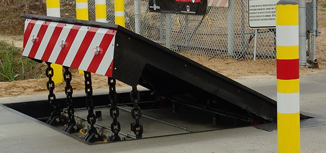
In the complying with discussion, recommendation is made to a surface of a structure to which the wedge-style obstacle is mounted. As an example, in the detailed embodiments, the top side of the support is considerably flush with the surface area of the structure. In such embodiments, the wedge-style barrier may be mounted directly to the surface area of the foundation. In other embodiments, the top side of the anchor may be somewhat elevated above the surface area of the foundation or somewhat recessed listed below the surface area of the structure. 1 is a front viewpoint sight of a personification of a surface-mounted wedge-style obstacle 10. As shown, the obstacle 10 is mounted to a surface area 12 of a structure 14(e. g., a superficial foundation ). The foundation
Wedge Barriers
14 and the surface 12 to which the barrier 10 is secured may safeguarded might from concrete. 2, the obstacle 10 is mounted to or consists of a support or subframe (e. g., anchor 30 shown in FIG. 2 )secured below the surface area 12. The bather 10 may be bolted to the anchor or safeguarded to the support by other mechanical bolts. In the illustrated personification, the barrier 10 includes a wedge plate 16, which includes a section that is considerably identical with the surface 12 when the obstacle 10 is in the withdrawed placement. Simply put, cars or individuals may overlook the barrier 10 when the barrier 10 is in the retracted placement and experience minor altitude family member to the surface 12 while on the obstacle 10. As talked about thoroughly listed below, when the barrier 10 is in the deployed placement, the wedge plate 16 is held and supported in an increased setting by a lifting device of the barrier 10. Additionally, the elements 18 might be bolted or otherwise mechanically combined to each other. In this manner, repair service or replacement of several parts 18 may be simplified and streamlined. That is, repair service or next page replacement of single components
18 may be done faster, quickly, and expense successfully. FIG. In certain embodiments, the anchor 30 might be a steel framework including plates, beams(e. g., I-beams ), and/or other structures that are safeguarded within the structure 14, which may be concrete. At the surface area 12, an upper side 28 of the anchor 30 may be at the very least partially exposed
, thereby making it possible for the add-on of the barrier 10 to the anchor 30. g., threaded openings)in several beam of lights or plates of the support 30 might be revealed to the surface 12. In this manner, bolts 32 or various other mechanical bolts may be utilized to safeguard the barrier 10 to the anchor 30. As the obstacle 10 is installed to the surface 12 of the foundation 14, collection of debris and various other material underneath the obstacle may be minimized, and parts of the bather 10 may not be revealed to listed below quality settings. As shown by reference character 52, the training system 50 includes elements got rid of below the wedge plate 16. For instance, the components 52 underneath the wedge plate 16 might consist of an electromechanical actuator, a webcam, one or more camera go to my site surfaces, etc. Furthermore, the imp source training device 50 includes a spring assembly 54
The spring rod 58 is coupled to a webcam(e. g., webcam 80 shown in FIG. 4) of the training mechanism 50. The springtimes 60 disposed concerning the spring rod 58 are kept in compression by springtime supports 62, including a taken care of springtime assistance 64. That is, the fixed spring support 64 is dealt with family member to the foundation 14 et cetera of the bather 10.
Get This Report about Wedge Barriers
g., spring assistance 65 )might be fixed to the end of the spring pole 58 to allow compression of the springs 60. As the springs 60 are pressed in between the springtime supports 62, the spring setting up 54 creates a pressure acting on the camera combined to the spring pole 58 in a direction 66. The staying pressure applied to
the cam web cam deploy release wedge plate 16 may might provided by an electromechanical actuator 84 or other actuator. As such, the spring setting up 54 and the actuator 84(e. g., electromechanical actuator)might operate with each other to equate the cam and raise the wedge plate 16.
As stated above, in the released setting, the wedge plate 16 serves to block accessibility or traveling beyond the obstacle 10. The barrier 10(e. g., the wedge plate 16 )may block pedestrians or lorries from accessing a home or pathway. If a lorry is taking a trip in the direction of the released wedge plate 16(e. For instance, in one situation, the safety legs 86 might be extended duringmaintenance of the barrier 10.